
Unshaded roof area is valuable — but shade is not always all-or-nothing
The Department of Energy identifies tree cover as a key factor in rooftop solar suitability and notes that roof size, shape and slope also matter. NREL's PVWatts model treats shading as one of several system-loss categories, while nearby trees and structures can require more site-specific shading analysis than a generic default.
That means a roof with some shade is not automatically a “no solar” roof. A professional design may move modules away from an obstruction, use different roof planes, or model the remaining production. The right answer comes from the actual roof and sun path.
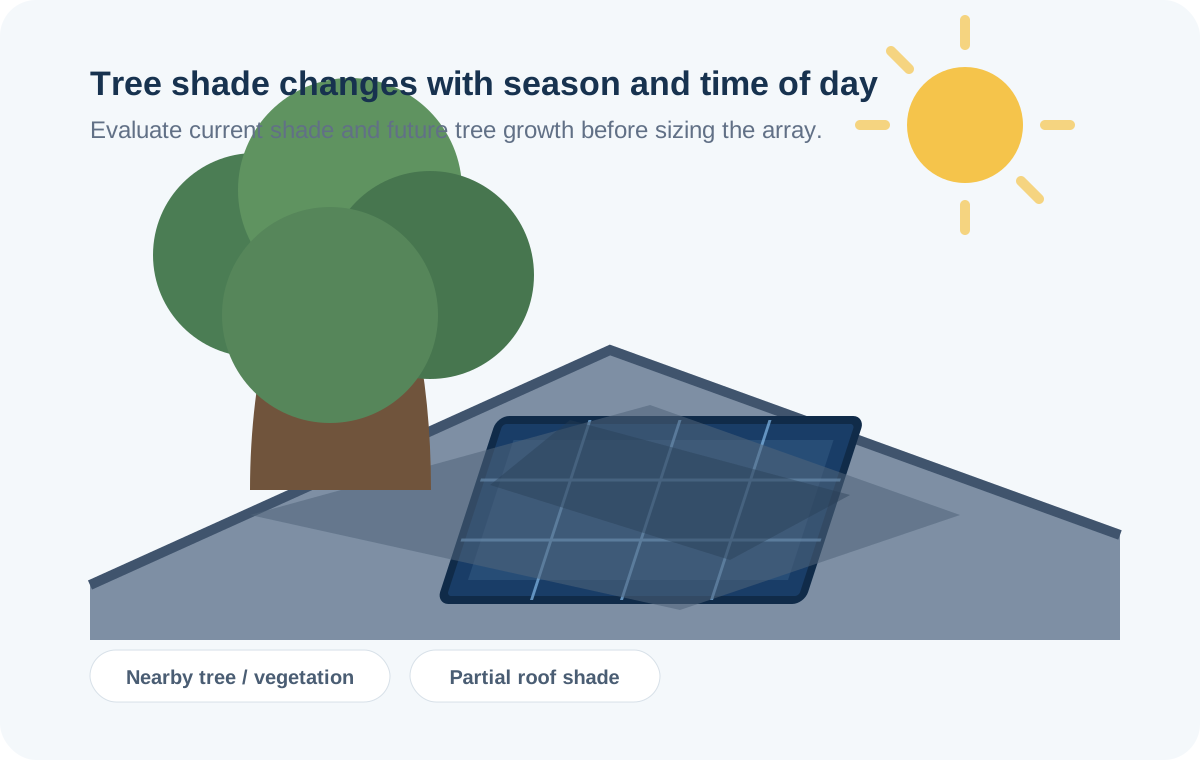
Trees and vegetation
The hardest shade to treat as a fixed obstruction because tree size, foliage and sun angle change over time.
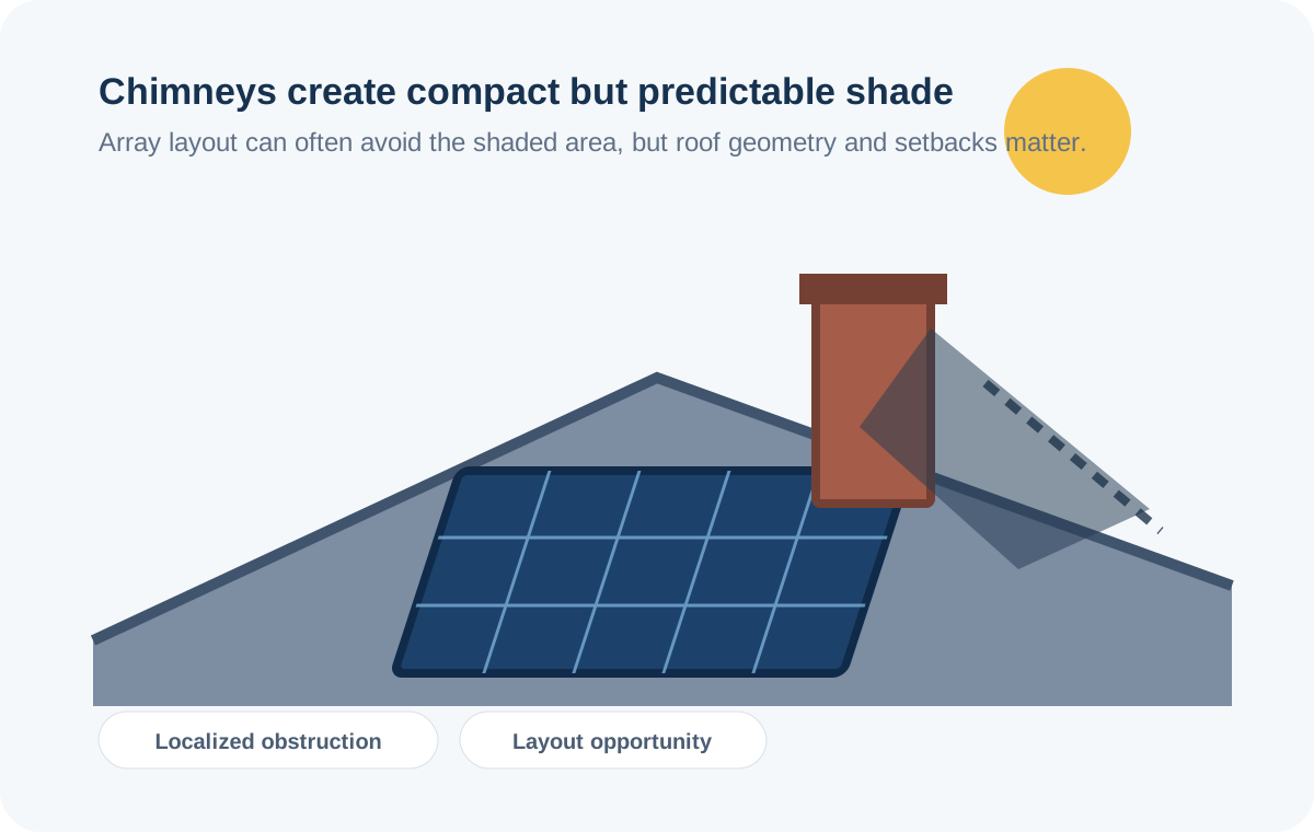
Chimneys
Usually a localized obstruction that can often be handled through array placement, but its shadow path changes with the sun.
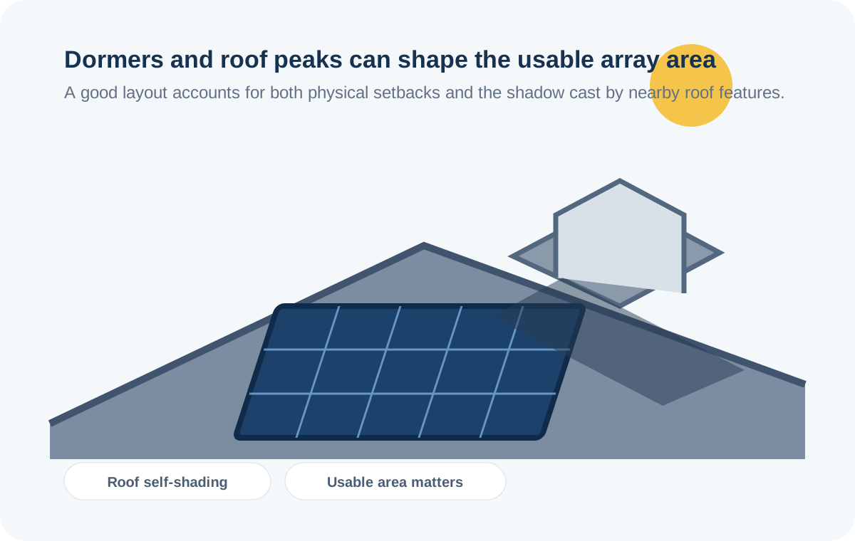
Dormers and roof peaks
Roof geometry can create both physical layout constraints and self-shading between roof planes or structures.
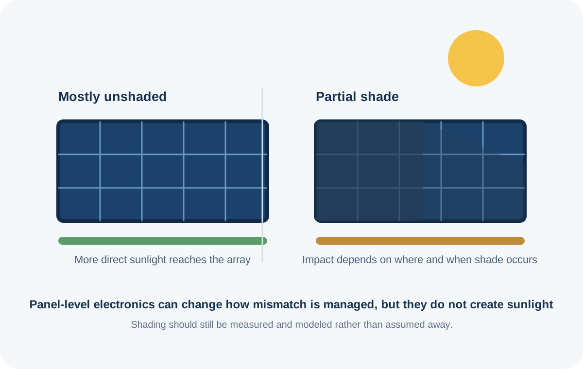
Partial shade
The effect depends on how much of the array is shaded, when it happens and how the electrical architecture manages mismatch.
| Shade source | Why it matters | What to check | Typical planning response |
|---|---|---|---|
| Trees | Foliage and tree height change with season and over the life of the solar system. | Current canopy, future growth, tree location, winter vs summer sun and afternoon exposure. | Model seasonal shade, consider array placement and discuss vegetation management where appropriate. |
| Chimneys | A vertical obstruction can create a moving shadow across nearby modules. | Chimney height, roof plane, array setback and the time of day the roof is producing. | Keep modules out of the most affected area when the economics of the layout make that sensible. |
| Dormers / roof peaks | They consume roof area and can shade neighboring modules or roof planes. | Roof geometry, available setbacks and the seasonal sun path. | Optimize module placement across usable roof planes and model the remaining production. |
| Nearby buildings | Large fixed structures can block part of the solar horizon, especially at lower sun angles. | Building height, distance, direction and seasonal sun path. | Use roof-level or site-level shading analysis rather than assuming a simple percentage loss. |
Plan for the tree you will have, not only the tree you see today
Trees are especially important because their height and canopy can change after the solar array is installed. A tree that is harmless in a satellite image today can become a recurring source of shade later.
Season also matters. Deciduous trees may have very different shading profiles in winter and summer, while evergreen trees can create a more persistent obstruction. A serious solar proposal should account for the actual sun path and vegetation, not just a single midday snapshot.
Questions for the installer
- How was tree shade modeled across the year?
- Does the design account for expected tree growth?
- Which roof planes are most affected?
- What production change occurs if the tree is left untouched?
Small obstructions can still influence panel placement
Chimneys are often easier to work around than trees because their position and height are fixed. The challenge is understanding the shadow path and balancing a slightly smaller array against the production gained by placing modules elsewhere on the roof.
Do not assume a chimney shadow is the same at 9 a.m., noon and 4 p.m. The sun's position changes throughout the day and across seasons.
Look for
- Chimney height above the roof plane
- Direction of the affected roof plane
- Module setbacks and fire-access requirements
- Whether the proposed layout simply avoids the obstruction
Physical fit and solar exposure are separate questions
A dormer can make a roof look large while leaving less usable area than the satellite image suggests. Its own roof plane, walls and adjacent peaks can also create self-shading.
This is why a roof analyzer should be treated as a starting point. Address-level models can identify roof segments and solar potential, but the installer still needs to turn those measurements into a code-compliant module layout.
Use both tools
- Roof Analyzer for address-level roof geometry
- Roof Solar Calculator for manual area checks
- Solar Calculator for production modeling
Microinverters and optimizers can manage electrical effects — not replace sunlight
Module-level power electronics can change how a system responds to mismatch between modules, which can be valuable on roofs with complex shade patterns. But electronics cannot recover sunlight that never reaches the panel.
The practical decision is therefore to combine good physical layout with an electrical architecture suited to the roof. If a large portion of a roof is regularly shaded, reducing the shaded area may matter more than selecting a more expensive inverter architecture.
A useful screening rule — not a substitute for a shade study
Older DOE Building America guidance gives a rough rule of thumb that a potential shading structure may be kept about twice as far away from the solar equipment as the structure is tall. Treat that as a screening heuristic, not a universal design requirement: the actual shadow depends on latitude, season, azimuth, height and distance, and a professional design can use more precise sun-path or site modeling.
NREL's PVWatts calculator includes shading among its system-loss inputs, while its documentation cautions that nearby trees or structures can require more appropriate external shading analysis or an on-site survey.
Primary sources
The illustrations are simplified homeowner diagrams, not installation instructions or a substitute for an installer shade study.